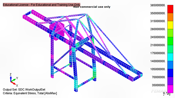
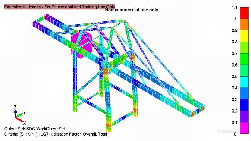
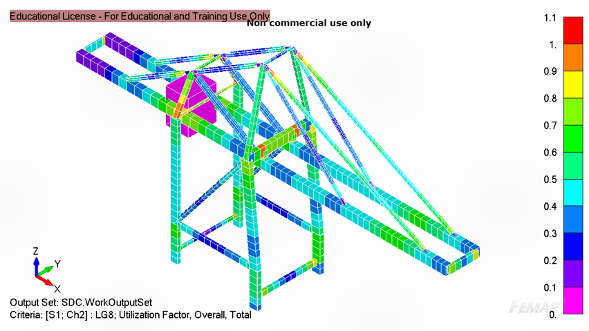
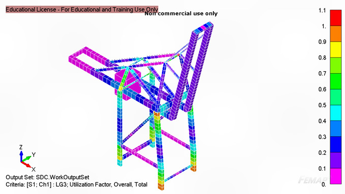
I learnt how to apply the structural theory I had learnt in the first two years of university into the design of a product – a ship-to-shore crane. This involved learning about finite element analysis using FEMAP and estimating load cases (i.e. lifting container, moving crane, wind etc) based on industry standards (NEN2018). Then I optimised the crane to achieve the maximum utilisation factor (maximum stress without exceeding safety factor) for stress, fatigue and buckling in normal and storm conditions under all load conditions.
I was introduced to finite element (FE) theory to understand the assumptions in the FE model such as triangular vs quadrilateral elements and clamped vs simply supported. I also learnt some structural theory on Palmgren-Miner fatigue, localised plate buckling and the differences between element types: bar, beam, shell, plate, plane and solid elements.
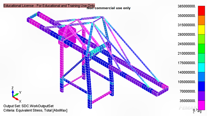
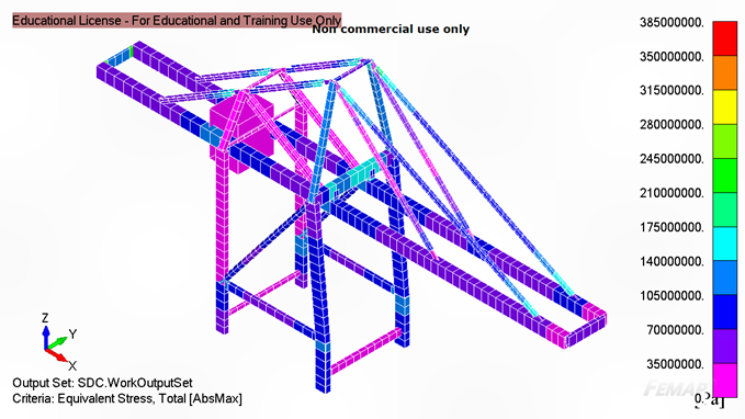
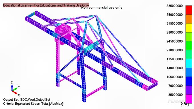
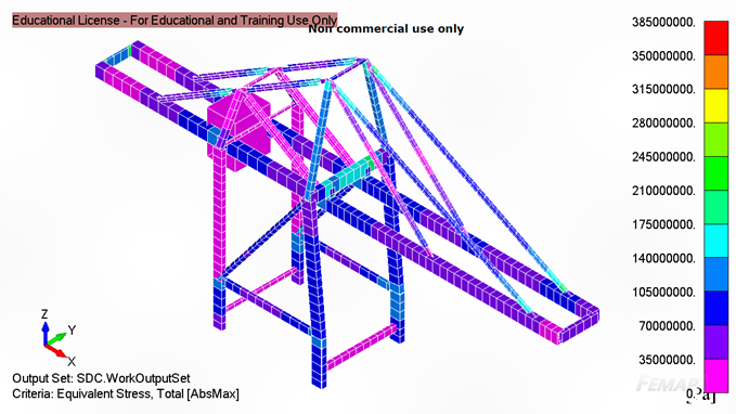
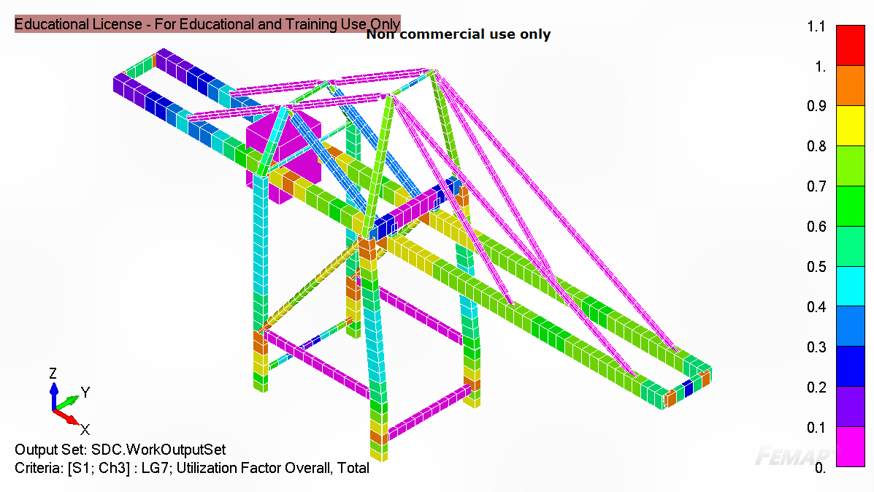
The animation at the beginning shows the exaggerated displacement of the crane for the mass of the trolley and container only (no movement or wind loads), as the container is picked off the ship and moved ashore. The images below show the maximum utilisation factor of each element under any load condition. Note: many of the elements in the buckling diagram are pink (zero utilisation) because they are in tension and the engine room is also pink under all scenarios as it is non-structural.
In total, 188 load cases were analysed for different trolley positions, trolley movements, crane movements, wind directions and emergency situations. The following are some examples of the load situations for the forward-most trolley position:
- Load Case 1: Trolley at front of crane - crane moving left - trolley moving forwards
- Load Case 2: Trolley at front of crane - crane moving left - container being hoisted up
- Load Case 3: Trolley at front of crane - crane moving left - trolley moving backwards
- Load Case 4: Trolley at front of crane - crane moving left - container being lowered down
- Load Case 5: Load Case 1 + sidewards wind
- Load Case 6: Load Case 1 + forwards wind
- Load Case 7: Load Case 1 + backwards wind
- Load Case 8: Trolley at front of crane - crane crashing into another crane
- Load Case 9: Trolley at front of crane - trolley crashing into front buffer