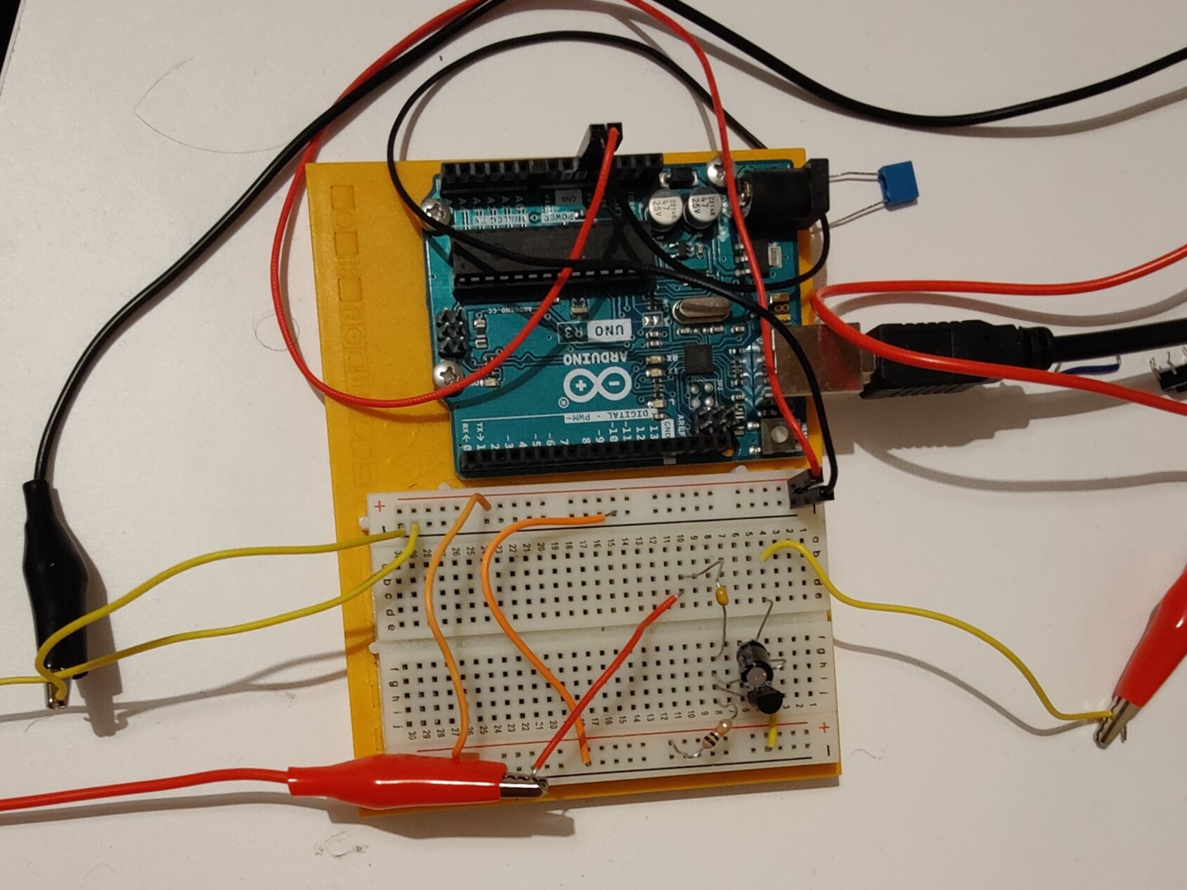
An electric guitar pedal is a device that alters the signal between the guitar and amplifier to create interesting audio effects. I thought it would be interesting to learn about electronics and some electrical engineering, so I prototyped a very simple distortion pedal using a breadboard. The pedal works by boosting the signal with a transistor and then clipping the signal with a diode to generate a distorted output signal (note: the Arduino is just for power, it serves no other functionality).
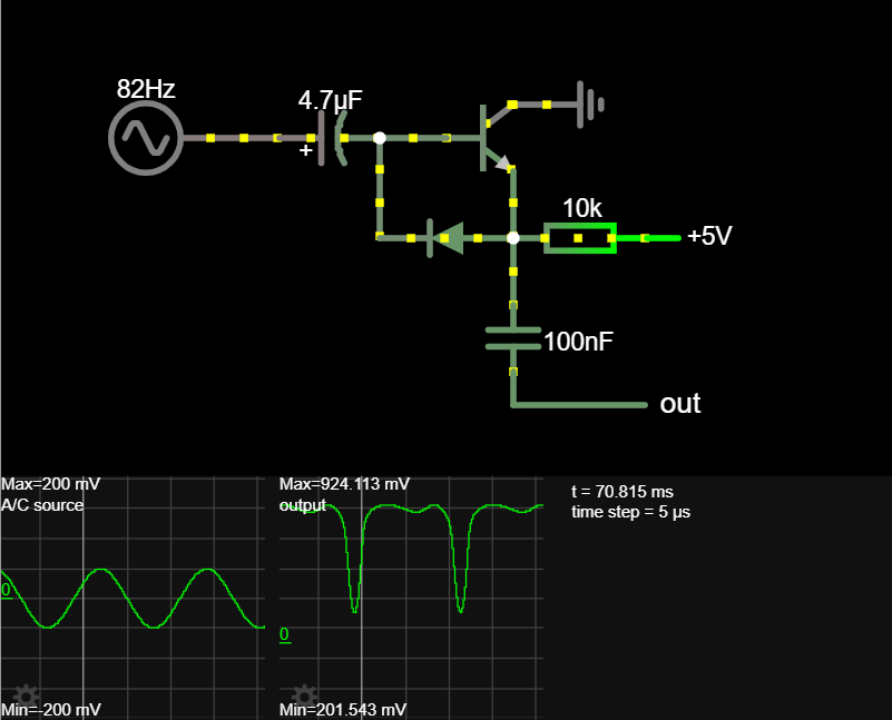
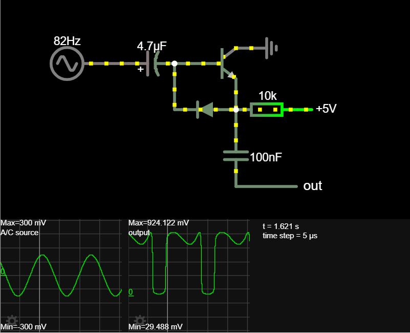
Figures 4-7 show how a sine wave is transformed into a kind of square wave which gives the typical fuzzy sound of a heavily distorted guitar. It can be seen the output signal depends on the frequency, from the lowest string E2 (82 Hz) to high notes such as E5 (660 Hz) and on how hard the string is plucked (200 or 300mV). I used an online tool called Falstad.com to help me understand the impact of adding/changing components.
To improve the guitar pedal, I’d like to add the ability to vary the voltage output (i.e. volume) as it currently only outputs at a single volume. Also, the pedal should be able to vary the amount of distortion by allowing some of the signal to bypass the transistor. Once the electrical circuitry is complete, I hope to solder the components together and put in a robust casing.